Leaderboard


Popular Content
Showing content with the highest reputation on 12/23/23 in all areas
-
It adds a little weight but it's worth it to me.1 point
-
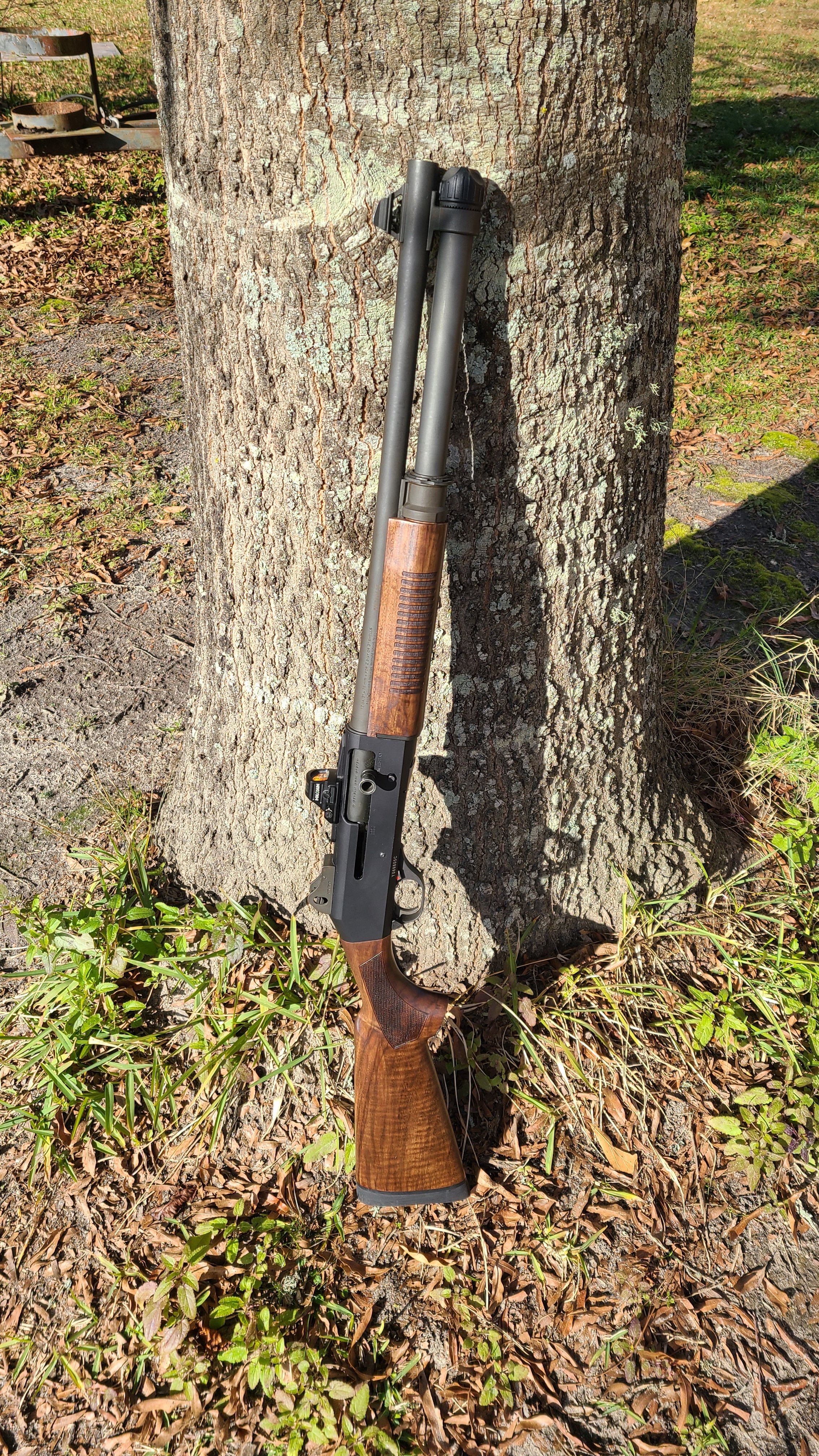
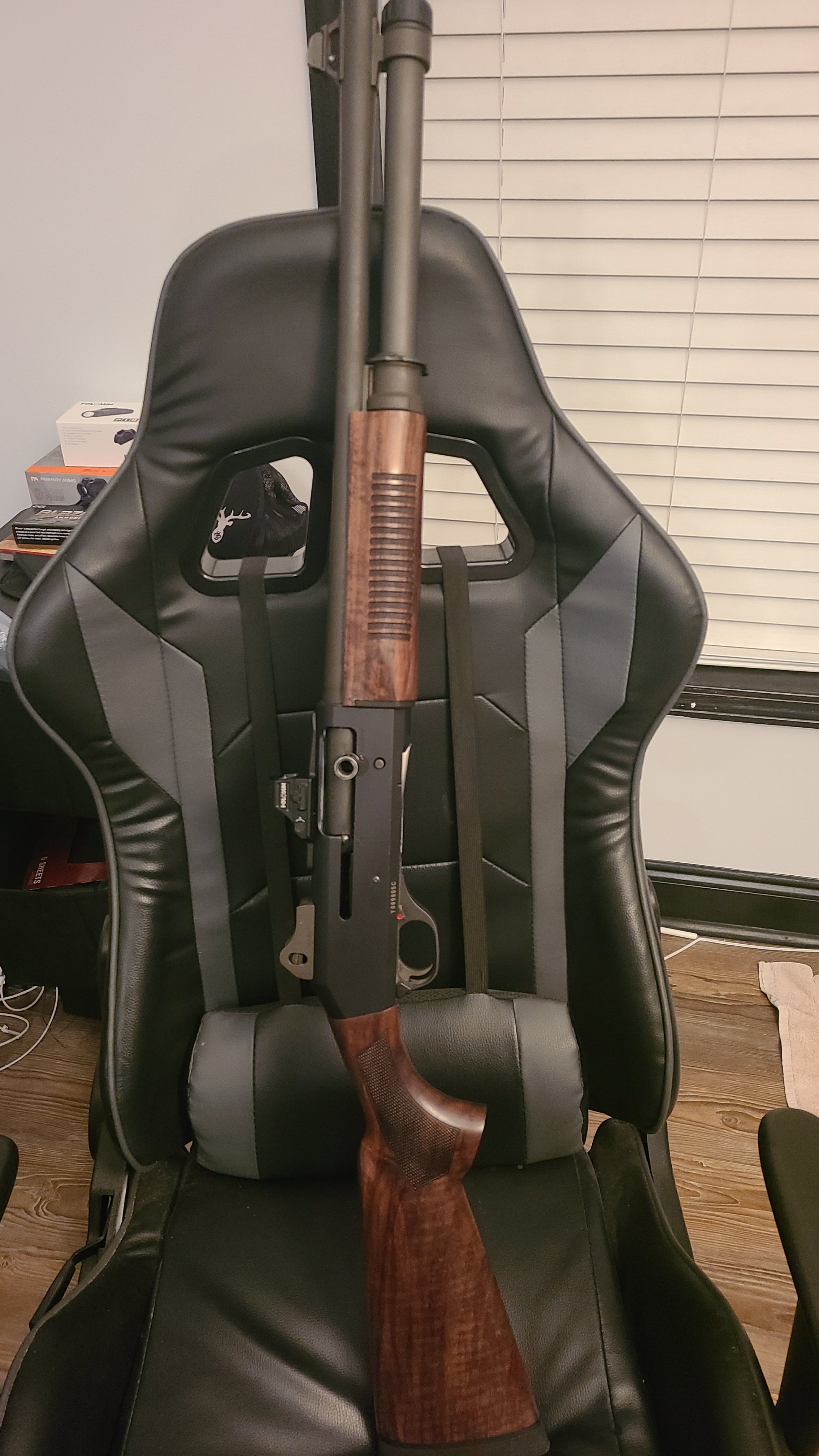
Pity, as much as I like the walnut stocks, having to scrape, sand, mill or drill for proper fitting should not be a hit or miss when purchased. Neither should the correct bolt or any other modification for that matter. My 2¢. Alpha33 out.......1 point
-
Thanks a ton! Exactly what I was looking for1 point
-
I got mine from Lowe’s. M8-1x601 point
-
No sling mount kind of sucks. Not a huge fan of the Mesa Tactical Urbino style attachment system for the stock. You had best be really careful tightening the bolt into the receiver extension. That snap ring will not prevent the stock screw from backing out during disassembly. Do not use thread locker on this bolt or you’re going to have a really bad time. The stock screw will come out of the receiver extension and be stuck on the end of the attachment bolt deep inside the wood stock. Not a huge fan of how they carved the handguards. They didn’t use the same piece to keep the grain of the wood consistent. Most Benelli owners would pay more for a better made product.1 point
-
Can you explain how this will damage the carrier latch?1 point
-
I’ve got two M4s - one I’ve had for 10+ years and one a few months old. I’ve literally done what OP described at least a thousand times with no ill-effect. Works just as well with the new gun. It’s 6 or 7 rounds in an entry gun depending upon the round.1 point
-
Forward Recently, I’ve had a few requests to do a disassembly/reassembly guide for the trigger pack of the Benelli M4. Today I had some spare time to kill, so I decided to try to tackle it. This manual can be used as a guide for pretty much any Benelli shotgun out there. Not everyone needs to do a full disassembly. They may be doing 922® upgrades or simply changing out their safety button. Perhaps you want to have your carrier welded up? You can jump around through the photographs and see what is needed to get the assembly apart to do your job. In this tutorial, many of the images will have lines on them indicating what you cannot see inside of the parts. I used the color blue to indicate the position of the tools such as punches. I used green to indicate the position of the roll pin or other type of assembly pins. White and black indicate the general assembly. Note: The trigger pack I am using is a spare complete trigger pack with a Geisselle hammer installed. The Tools Before proceeding into this tutorial, I would advise that you have some proper gunsmith grade tools. You do not need hundreds of dollars’ worth of tools, but you do need the basics to prevent marring your work. Proper tools will also keep the swearing to a minimum. This job we’re about to perform will cause some swearing. You will be required to manipulate many small spring loaded pieces that must be aligned perfectly. It might be pretty miserable to perform if you have big sausage fingers. Take this under advisement before you’re forced to make the walk of shame to the local gunsmith with a shoe box full of parts. Naturally, if you get stuck somewhere, get a hold of me and I’ll help you in any way that I can. If you’re still stuck or have broken something, you can send the assembly to me to repair. All I will charge is the cost of shipping it back and the cost of any needed parts. The same applies if you want something repaired or if you want 922® compliance parts installed and do not feel you can complete the task. I’ve done many installs for locals and other members on this forum in the past. If I have the parts on hand or you are sending them with the item, I usually have the work back in the mail to you the next morning. 1/16 Punch 3/32 Punch Snap Ring Pliers Dental Pick Alignment Tools Assembly Block Brass Hammer Rawhide Mallet1 point
-
Here we are disassembling the Trigger Assembly. Use a 1/16" punch to tap out the Disconnector Pin. Here the Disconnector Pin has been removed. The Disconnector, the Disconnector Plunger and the Disconnector Spring now can be pulled out of the Trigger.1 point
-
Here we are removing the Rear Trigger Pin. There isn’t really much purpose to removing this pin unless you’re doing a complete tear down for some reason. This pin does not need to be removed in order to pull out the Trigger Assembly. You will notice that the Trigger Pin taps out quite easily.1 point
-
Here the Front Trigger Pin has been removed and the Trigger Assembly has been pulled out of the Trigger Guard. The Shell Release Lever is free and can be removed now. Here is the Trigger Assembly removed from the Trigger Guard.1 point
-
Trigger Disassembly Here we are going to remove the front Trigger Pin. This pin also retains the Shell Release Lever Spring. Tap out the pin with an appropriate size punch and hammer from either side. As you tap the punch thru the assembly, the punch will act as a slave pin and hold the Trigger to the Trigger Guard Assembly.1 point
-
Here is the Hammer, Hammer Spring and Hammer Spring Cap pulled free from the Trigger Guard Assembly. Note the hole in the Hammer. This is what the Trigger Pin Bushing inserts thru. Here the Shell Release Lever has been pulled off of the Trigger Guard. Try not to bend the Shell Release Lever Spring when you separate the parts.1 point
-
Here you can see how the Breech Latch Pin comes apart. Here you can see the Carrier Plunger and the Carrier Spring. The spring simply slides over the plunger.1 point
-
Here, the Trigger Pin Bushing has been removed. The Trigger Pin Bushing acts as an alignment pin that holds the Carrier, Shell Release Lever and Hammer to the Trigger Guard. So once the Trigger Pin Bushing is pulled out, everything will start to fall apart if you like it or not. Once the Carrier pulls away from the Trigger Guard, the Carrier Plunger/Carrier Spring will simply fall out of the Breech Latch. The Shell Release Lever will still be retained to the Trigger Guard by the Shell Release Spring that can be seen along the top of the Shell Release. Pull the Hammer, Hammer Spring Cap and Hammer Spring out of the Trigger Guard and set them aside. Here is a close up of the Carrier, the Breech Latch and the Breech Latch Pin. To disassemble this part, simply tip the Carrier over and the Breech Latch Pin will fall out. The Breech Latch will then simply pull away from the Carrier.1 point
-
Now with the snap ring removed, you may push the Trigger Pin Bushing out from left to right. Be sure the hammer is decocked before doing this. Since we’re doing a full disassembly, push the Trigger Pin Bushing completely out with a punch or an alignment pin. As you push the Trigger Pin Bushing out, the Shell Release Button will likely unhook from the top of the Hammer Spring Cap as shown in my photograph above. As you pull the Trigger Pin Bushing out, be careful not to dislodge the Shell Release Lever yet. There is a small spring attached to it that is easy to damage.1 point
-
Disassembly of the Trigger Assembly The first step to disassembly of the trigger pack is to remove the Trigger Pin Spring (also known as a snap ring) from the left side of the trigger assembly. To do this, you need a pair of snap ring pliers with an appropriate size pin size. I believe it is best to use the .050” diameter pins. Apply pressure with the snap ring pliers so that the snap ring expands and allows you to remove it from the Trigger Pin Bushing. Note the grooves along the side of the Trigger Pin Bushing. These grooves are what the snap ring seats into. You must align these grooves up when reassembling or you risk damaging the Trigger Pin Bushing by allowing the snap ring to squeeze the bushing incorrectly.1 point


This leaderboard is set to New York/GMT-04:00